Audio Production
Complex IQ sampling: channel order and frequency direction
Complex IQ sampling preserves signed frequency through paired channels. Trace quadrature signals, channel conventions and mismatch-created mirrors.
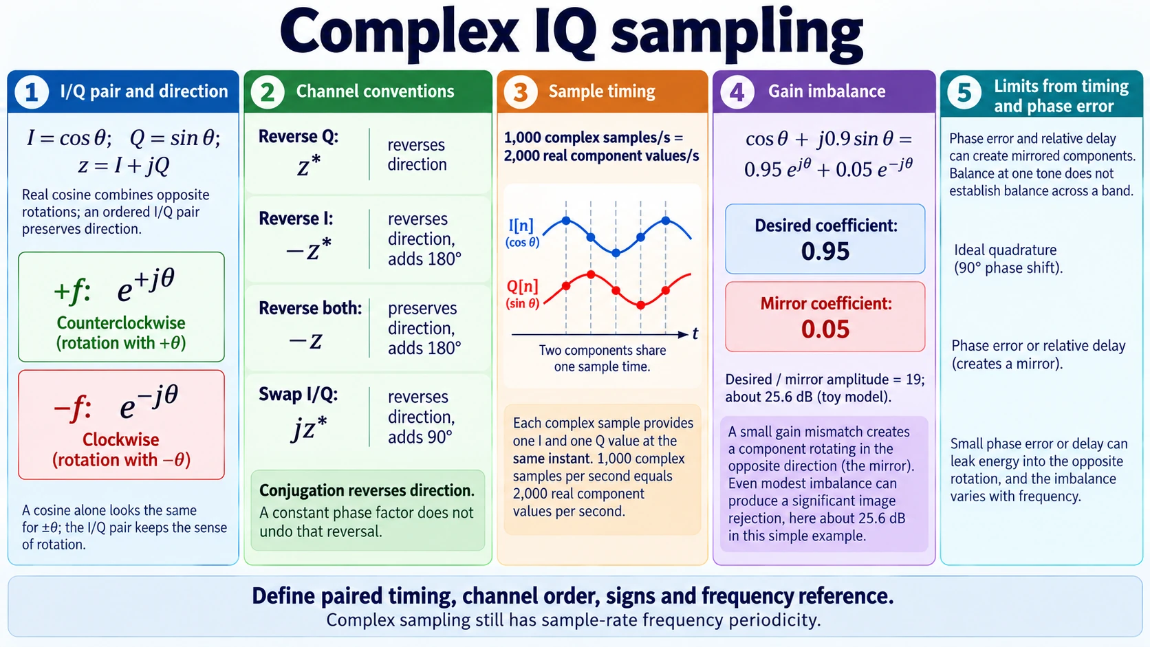
A real cosine can be written as the sum of two complex rotations traveling in opposite mathematical frequency directions. Recording that cosine alone preserves their combined real value. Recording a correctly related cosine-and-sine pair allows the two values to form a complex quantity whose rotation direction remains visible.
complex IQ sampling records the two related components as an ordered pair. I denotes an in-phase component and Q a quadrature component. The pair is interpreted with an explicitly chosen ordering and sign convention, commonly z[n] = I[n] + jQ[n]. Two channels by themselves are insufficient: their relationship and their common timing must support that interpretation.
The direction refers to frequency in the complex representation and its defined reference frame. It is not a claim that a voltage has become an imaginary physical quantity. I and Q are real measurements. The complex number is a useful way to retain two related components and operate on them together.
Compare a real cosine with quadrature signals
For a continuous-time reference, take I(t) = A cos(2πft) and Q(t) = A sin(2πft), with A positive. Euler’s identity combines them into z(t) = A ej2πft. At time zero the point lies on the positive real axis. As time increases for positive f, it moves toward the positive imaginary axis and rotates counterclockwise under the usual plotting convention.
The cosine alone satisfies cos(2πft) = cos(−2πft). Its real values therefore cannot distinguish those two mathematical frequency signs. The sine changes sign when f changes sign. Keeping the ordered pair supplies the missing distinction: A cos(2πft) + jA sin(2πft) differs from A cos(2πft) − jA sin(2πft).
A real cosine’s complex exponential expansion is A cos(2πft) = (A/2)ej2πft + (A/2)e−j2πft. Both directions appear with equal amplitude. A real-valued waveform’s spectrum has conjugate symmetry, so its negative-frequency portion is tied to its positive-frequency portion rather than providing an independently chosen second spectrum.
In a properly formed complex pair, the two channels contain quadrature signals with the stipulated relative phase and scale. Their combination can retain one rotation direction without requiring an equal conjugate component in the other direction. This gives a complex spectrum a useful freedom that an arbitrary real waveform does not have.
Signed frequency describes rotation relative to a convention
Sampling the pair at times nT gives z[n] = A ej2πfnT. Successive complex points advance by angle 2πfT. A positive angular step rotates one way, while a negative angular step rotates the other. The associated signed frequency records that direction under the chosen complex-number convention.
For a hypothetical pair sampled at 1,000 complex samples per second, a component at +100 hertz advances by 36 degrees per sample. A component at −100 hertz advances by −36 degrees. Their I values alone are the same cosine sequence, but their Q values have opposite signs. The ordered pair distinguishes them without requiring a denser sequence of sample times.
The frequency reference must still be named. In a system translated around a reference oscillator, positive and negative offsets can identify opposite sides of that reference. Which physical side maps to which mathematical sign depends on the mixing and channel conventions. A graph marked only “positive I/Q frequency” is incomplete if the hardware sign convention is unknown.
A complex sequence also repeats its discrete-time frequency representation at multiples of its sample rate. The direction distinction operates within a chosen frequency interval and representation; it does not abolish sampling periodicity. Use the half-open interval [−fs/2, +fs/2) to represent one discrete-time frequency period; the two endpoints would represent the same sampled rotation. No claim about unbounded distinguishable frequencies follows from using two components.
Channel swaps and sign reversals change the interpretation
Begin with z = I + jQ for the ideal cosine-and-sine pair. If Q is reversed while I stays fixed, the new quantity is I − jQ = z*. Complex conjugation reverses the rotation direction. A component that appeared at +f now appears at −f under the original display convention.
Reversing I while keeping Q gives −I + jQ = −z*. The extra minus sign adds a phase rotation of half a turn, while the conjugation still reverses frequency direction. Reversing both channels gives −z, which rotates the phasor by half a turn without reversing its direction. These distinct results help locate a wiring or software-convention error.
Swapping the channels produces Q + jI = jz*. This also reverses the frequency direction and adds a quarter-turn phase factor. A swap should therefore not be treated as a harmless relabeling unless every downstream convention is changed consistently. The amplitudes can look plausible while the signed spectrum has been reflected.
These calculations concern the interpretation of the samples, not a fault diagnosis for a particular product. A controlled test can use a known pair and verify the expected rotation before applying the chain to an unknown signal. Record the channel order, whether Q enters with plus or minus j, and the reference used to define positive frequency.
The same discipline matters when moving data between programs. One file format may store I first and Q second, while a processing library may expect another arrangement. An unexplained conjugation can reverse a frequency-offset estimate without changing the total signal power. A power plot alone is therefore an inadequate check of the sign convention.
Complex sample rate differs from stored component count
One complex sample consists of two real component values associated with one sample time. If a system produces fs complex samples per second, storing both components requires 2fs real scalar values per second before accounting for coding, metadata, or compression. That doubled value count is a storage fact, not a doubled cadence of complex observations.
The hypothetical 1,000-complex-sample-per-second sequence contains 1,000 I values and 1,000 Q values each second. A file may interleave them as I0, Q0, I1, Q1 and so on. Interleaving does not mean that Q0 belongs to a later independent sample time than I0. The paired interpretation requires their physical timing relationship to be known.
A real sequence and a complex sequence at the same numerical sample rate carry different spectral constraints. The real sequence has conjugate symmetry. The complex sequence can contain independent content on both sides of zero within its chosen total frequency interval. This is why counting scalar values alone misses the representation’s purpose.
Conversely, two unrelated real channels do not become a meaningful complex measurement merely because software combines them with j. They may represent unrelated signals, have unequal delays, or lack the reference relationship required by the application. The arithmetic is possible, but the resulting spectrum may not correspond to the intended physical quantity.
Amplitude mismatch creates a mirrored component
Now let the intended I channel have scale a and the Q channel scale b, while their phase relationship remains exact. The pair is z(t) = a cos(θ) + jb sin(θ), where θ = 2πft. Expanding the two trigonometric functions gives z(t) = ((a + b)/2)ejθ + ((a − b)/2)e−jθ.
When a equals b, the reverse-direction coefficient is zero. If their scales differ, the reverse component remains. This is an unwanted mirrored spectral component generated by imperfect balance of the pair. It can appear despite an input that fits the stipulated one-direction model.
For a hypothetical example, take a = 1 and b = 0.9. The desired coefficient is 0.95 and the mirrored coefficient is 0.05. Their magnitude ratio is 19 to one, corresponding to roughly 25.6 decibels when expressed as 20 log10 of that ratio. This is a calculation for the ideal mismatch model, not a measured rejection specification.
The result also shows why simply normalizing the overall magnitude is insufficient. Multiplying the entire complex sequence by one gain changes both coefficients together. It does not remove the imbalance between I and Q. Correction must address the actual mismatch, and evidence is needed to establish that the correction is appropriate over the frequencies and conditions being used.
Phase error and timing mismatch also spoil the pair
If Q is not exactly a quarter-cycle from I in the intended representation, combining the channels no longer cancels the unwanted direction as intended. A phase error creates a mirrored component even when their amplitudes are equal. The amount depends on the phase error and the signal conditions used to characterize it.
A relative delay between channels produces a frequency-dependent phase difference. A delay that looks small at a low frequency can produce a larger angular error at a higher frequency. A calibration at one tone therefore does not automatically establish balance across an entire band. Channel scale and delay may also vary with operating conditions.
The sampling-clock-jitter guide describes how acquisition-time uncertainty changes a measured amplitude according to local waveform slope. That timing model matters when combining quadrature signals: a common shift and a relative channel delay need not have the same effect on the pair. The related guide analyzes individual sample errors; channel alignment requires the additional relative-timing evidence described here.
The FFT-zero-padding guide explains why adding zeros makes a spectral grid denser without adding observations or improving the original record's resolving information. That distinction also applies when displaying signed frequency from I/Q data. A denser plot cannot establish channel order, correct a conjugated pair or repair an analog phase mismatch. The frequency convention and measured samples still determine what the spectrum represents.
To investigate an apparent mirrored component, verify channel order and signs first, then measure the relative gain and phase under a known stimulus. Preserve the raw paired data before correction. A mirror caused by a convention error calls for a different repair from one caused by frequency-dependent channel imbalance.
Product descriptions do not establish an I/Q acquisition contract
The ZT-703S handheld oscilloscope, multimeter and waveform generator is listed with two oscilloscope channels and waveform storage or export. Related traces provide a useful setting for illustrating the component pair. Using exported measurements as I/Q data would require separate evidence of matched timing, relative gain and phase, and the selected frequency-direction convention.
The Focusrite Scarlett 4i4 fourth-generation recording bundle provides a four-input USB-C audio interface, four balanced outputs and recording accessories according to its listing. Compatible audio components can illustrate paired-data arithmetic. A radio-frequency acquisition mode, channel-balance calibration and a shared reference cannot be inferred from the number of audio inputs.
A defensible use of complex IQ sampling specifies the paired timing, channel order, sign convention, reference frequency, and relevant mismatch evidence. With those facts in place, an ordered pair preserves rotation direction that a real cosine alone cannot distinguish. Without them, the complex arithmetic may still run correctly while describing the wrong direction or adding a mirrored component.