Audio Production
Timer input capture and event-time boundaries
Timer input capture separates interrupt latency from event timestamp acquisition. Compare hardware capture, software reads, quantization and retention limits.
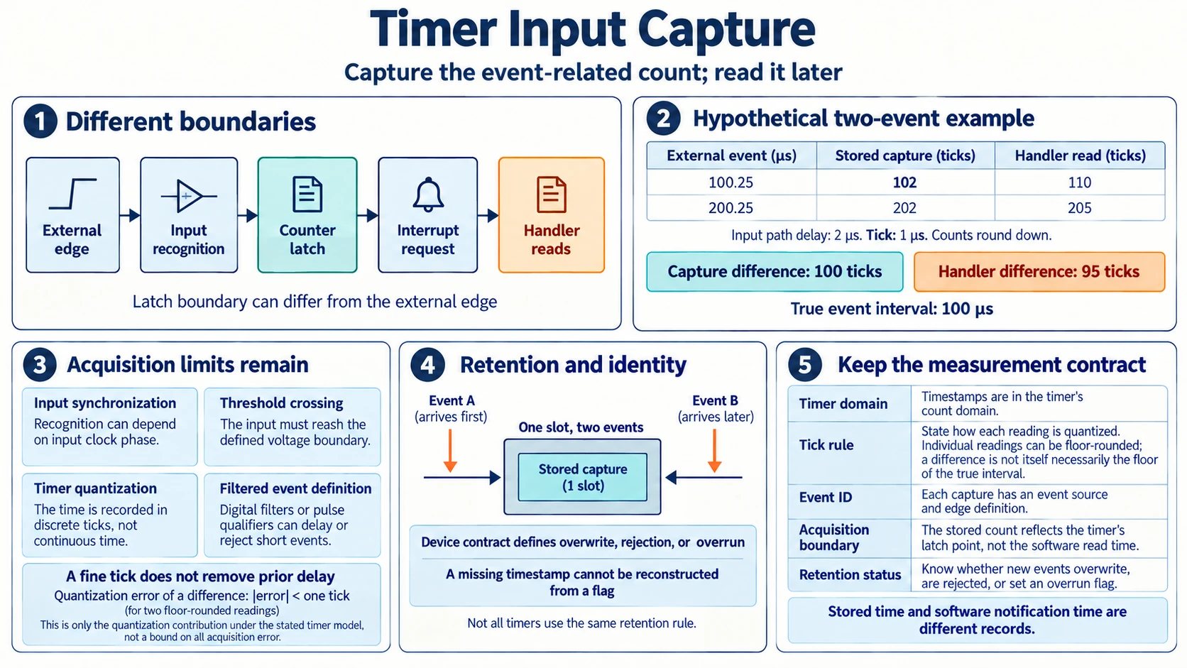
An interrupt handler runs after an external event has been detected and after the processor is ready to service it. Reading a timer inside that handler therefore records a later boundary. If the delay varies, the timestamp varies even when the external event timing does not.
Timer input capture changes where the counter value is acquired. Hardware latches a value at a defined event-related boundary, and software can read that retained value later. The service delay still affects when software learns about the event, but it need not be added to the stored event time.
Hardware capture still has limits set by input detection, synchronization, timer resolution, and storage capacity. Those belong to the measurement contract alongside the difference between capture and later service.
How interrupt latency belongs on the event timeline
Separate the external edge, its recognition by the input path, the counter-latch event when present, the interrupt request, the start of the handler, and the later software read. Those stages need not occur at the same time, and their ordering must come from the actual implementation.
An input can pass through threshold detection, conditioning, or clock-domain synchronization before it is recognized. The interrupt mechanism then asks the processor to run software. Other work or masking can delay service. A counter read adds any delay between handler entry and the instruction that obtains the value.
A timestamp taken at that read reflects the read boundary. If the intended measurement is the external edge, the earlier intervals are additional error or delay terms that need to be characterized. Calling the routine an event handler does not move its read back to the event.
The monotonic-clock guide supports the interpretation of interrupt latency by separating timestamp resolution from delay before an event is observed. A fine timer unit describes representation; it cannot remove a delay that occurred before the software read. The guide also requires a stated domain, rate, and lifecycle for duration comparisons. Those contracts apply to interpreting the saved count, while the peripheral documentation must identify the actual interrupt and latch path.
A fixed service delay and a varying service delay have different consequences. A known constant can shift an absolute timestamp consistently. A variable term changes comparisons between events, and subtracting one nominal constant cannot remove every occurrence.
How event timestamp acquisition can precede service
In a capture arrangement, the input path triggers hardware to retain a timer count. An interrupt can notify software that the value is available. Reading the capture register later obtains the previously stored value rather than the timer's current value.
In hardware capture, the latch acquires the count before the later software read. Moving that boundary separates acquisition timing from service timing. Software still has to associate the stored value with the correct event and handle retention or overrun conditions.
The network-clock guide supplies a concrete event timestamp comparison: its four values name send and receive boundaries, with a separate receive-to-reply processing interval. That distinction matters here because a hardware-latch count and a later handler count name different boundaries. The network analysis concerns clock relationships and path delay, not a timer register design. A wrapping timer also needs its modulus and an interval bound or extra wrap evidence before a count difference becomes an unrestricted duration.
Hardware capture can preserve an event-related time despite later service jitter. It does not guarantee that the latched boundary equals the external edge. The difference includes the input acquisition path and any clock alignment required by the capture mechanism.
Documentation and applicable measurements must identify that boundary. A label saying capture does not establish which edge, filtered transition, synchronization stage, or timer clock produced the stored value.
Texas Instruments documents this separation in the TM4C123GH6PM timer's input edge-time mode. When a selected input event is detected, the current counter value is captured into snapshot registers and interrupt status is asserted. Separate registers expose the free-running value. The counter keeps running, while another selected edge replaces the captured snapshot. This is a concrete documented peripheral example, not a retention rule to assign to every timer.
Linux's Hardware Timestamping Engine documentation describes devices that monitor signals for state changes and automatically store timestamps when those changes occur. Its framework provides a timestamp-delivery path to software. The presence of a retained hardware time therefore needs to be distinguished from the later availability or handling of that record, with the provider's actual timestamp source and event definition retained.
A bounded comparison with changing service delay
Use a hypothetical timer ticking every microsecond, with a counter representation that rounds elapsed microseconds downward. The first external event occurs at 100.25 microseconds. Declare a fixed acquisition-path delay of 2 microseconds, so the latch boundary is 102.25 microseconds and its retained count is 102.
Suppose the handler's current-timer read occurs at 110.25 microseconds. That software read yields 110. The retained count and current count are different values because they represent different boundaries, despite using the same timer.
The second event occurs at 200.25 microseconds. With the same acquisition delay, its latch occurs at 202.25 and captures 202. This time the software read happens at 205.25 and yields 205.
The true event interval is 100 microseconds. Subtracting the two capture counts gives 100 ticks, matching that interval in this constructed example. Subtracting the two handler-read counts gives 95 ticks, because the software-service delay changed from ten microseconds after the first event to five after the second.
The agreement of the capture difference relies on the declared equal path delays, timer rate, and equal fractional positions relative to the ticks. It is not a universal zero-error claim. If input acquisition delay or tick phase changes between events, the capture difference can include their changes.
The absolute capture value also remains displaced from the external event by the acquisition path and quantization. A good interval difference can therefore coexist with an absolute timestamp bias. The measurement requirement determines which quantity needs evidence.
Synchronization and quantization remain limits
An asynchronous input may be recognized only after clocked input logic observes it. Its recognition can depend on arrival phase within a clock interval. A fixed number of synchronization stages does not automatically make the total external-edge-to-capture delay a constant physical duration for every phase.
The input path's acquisition timing contract belongs in the stored-count interpretation. A metastability probability calculation would require separate device characterization. A later valid digital event can still carry uncertainty about the original edge position.
Timer quantization introduces another term. With a floor-rounded timer of tick duration q, each stored reading is below its ideal timer value by less than q. The difference of two such readings has a quantization error magnitude less than q under that declared representation.
Other capture conventions can require different bounds. An event assigned to the next timer edge rather than a floor-rounded instantaneous reading uses another timing rule. The unit of the counter is not sufficient to identify which one applies.
Input filtering can also redefine the admitted event. A filter that requires persistence may reject a short pulse or recognize a transition later. That can be correct for its purpose, but the retained count then belongs to the filtered event boundary. The analysis needs to state which event it intends to time.
The external event definition also needs a voltage boundary for a physical edge. If the source marker describes the start of a rising ramp but the timer recognizes a threshold crossing, their difference depends on the ramp slope and threshold. A changing edge shape can alter the apparent delay even when the capture logic itself is unchanged.
For a stipulated linear ramp rising at one volt per microsecond, a threshold half a volt above its starting level is crossed half a microsecond after the ramp begins. A ramp with twice that slope crosses the same threshold after a quarter microsecond. These values describe the declared waveform geometry, not a universal input-detector delay.
A comparison should therefore identify whether it measures the ramp start, the voltage crossing, or a later recognized digital transition. Aligning those definitions avoids assigning a source-waveform change to software-service variation.
Retention can fail before software reads the value
Suppose a capture unit has one retained-value slot, and two events arrive before software consumes it. The hardware may overwrite the first value, retain the first and report an overrun, reject the second, or follow another documented rule. The capacity alone does not identify that rule.
If only one of the values remains, software cannot reconstruct both event times from the surviving count without additional evidence. A flag indicating that something was lost can expose incompleteness, but it does not supply the missing timestamps.
Faster draining or additional retention can improve the supported event rate, subject to the actual arrival pattern and service behavior. A favorable average rate does not prove that a brief burst fits the available storage. The retention contract should be checked against the relevant burst as well as steady operation.
A captured value read after an overrun must also be associated with the correct event. Using a fresh retained count with an old software event label creates an identity error even if both the counter and label look individually valid. Event ordering and overrun status belong in the saved evidence.
The Unbranded ZT-703S Electrical Testing listing, SKU 18623303850, describes a handheld oscilloscope, multimeter, and signal generator with waveform storage and export. An accessible conditioned electrical edge can provide an observation context for the timeline. Its trace still needs a justified relationship to the timer input and software-visible marker. The listing does not specify another peripheral's capture semantics, interrupt path, or retained-register behavior.
A scope record can help compare an accessible edge with a software-visible signal only if the signal's relationship to handler execution is justified. Toggling an output adds its own execution and propagation boundary. Its timing should not be silently equated with the counter-read instruction.
Recording accessories and four balanced outputs are included in the description of the Focusrite AMZFCS4I4CR3X Red 4i4 Kit, identified as SKU 1894010824. Its audio interface connects through USB-C and has four inputs. A compatible audio record can supply sample-index timing under its own acquisition contract. That context illustrates the difference between acquiring a value and processing it later. The listing supplies no microsecond input-latch timing or overrun state for a separate timer, and no mapping from audio sample time to that peripheral counter.
A retained count should be saved with the timer domain, tick definition, event identity, acquisition rule, and retention status. Those fields allow a later analysis to reject a duration claim when the stored value belonged to a different boundary or an incomplete event sequence.