Educational & Explainer Articles
Hand plane parts: sole, blade, mouth and cutting angle
Understand the sole, blade, frog, mouth and clamp, then connect bevel orientation, cutting angle, wood fibers and sole length to different planing tasks.
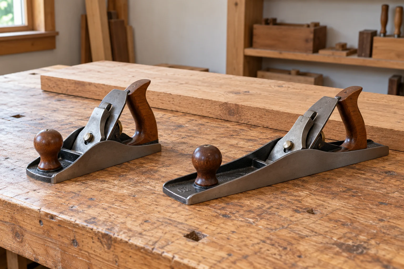
A hand plane combines a cutting edge with a surface that guides it across the wood. Its usefulness comes from the relationship between those parts: where the edge sits, how it meets the grain, where the shaving can travel and how much of the board the body bridges. Understanding hand plane parts gives you a way to interpret a tool description before deciding whether you need a smoother, a different blade arrangement or a different preparation task.
This guide follows the mechanism from the underside of the tool to the emerging shaving. The selected Stanley No. 4 and WoodRiver No. 62 are real catalogue examples, with different amounts of supplied detail. Manufacturer and practitioner material explains the general principles. No board was planed for this article, and no cutting result or delivered tool’s dimensions have been measured.
The sole provides the reference for the cut
Rockler’s hand-plane manual names the sole as the base, the iron as the cutting blade and the mouth as the opening through which the edge projects and the shaving emerges. Its component drawing places the front knob ahead of the blade assembly and the tote, or rear handle, behind it. These names locate the main pieces before the adjustment mechanisms become relevant.
Think about the cutting edge in relation to that underside. Blade projection describes how far the edge extends beyond the sole. The reference therefore travels with the tool: the question concerns the edge’s position relative to the surface supporting the plane. That relationship explains why an exposed blade length measured from the top would answer a different question. The useful view is the cutting edge at the mouth and the surrounding sole.
Blade projection and sideways alignment do different jobs
The Rockler drawing distinguishes the depth-adjustment wheel from the lateral-adjustment lever. The first changes blade projection and thus the depth of the cut. The second changes the edge’s sideways alignment relative to the sole. A control that increases projection does not, by that action alone, establish that the edge is evenly presented across the opening.
These give you two precise descriptions when reading a plane’s features: how far the edge is presented and how it is aligned across the tool. Keep both descriptions available when comparing adjustment systems. A catalogue statement about fine depth control leaves the alignment arrangement to its own evidence. The general principle is useful even when a particular plane combines adjustment functions in one mechanism; the two questions about the cutting edge remain distinct.
The frog, lever cap and cap iron support the blade assembly
Fine Woodworking’s Handplaning 101 describes the frog as the angled bed connecting the plane body to the iron. In the illustrated bevel-down assembly, a chipbreaker sits on the blade and directs shavings upward. The lever cap retains that assembly on the frog. These are separate physical roles within the same stack of parts.
Lie-Nielsen’s introductory guidance also distinguishes retaining pressure from blade adjustment: its bench-plane cap should allow depth adjustment while secured. That is a statement about its documented arrangement, rather than a universal screw setting. It helps explain why a description of a blade clamp and a description of an adjuster should both appear in a useful account of the mechanism.
The name cap iron is also used for the chipbreaker. Keep it separate from lever cap when discussing the assembly. Otherwise, a question about the piece contacting the blade can be mistaken for a question about the part retaining the whole stack. You can identify the part by its relationship to its neighbours before considering any adjustment or replacement. The exact hardware still belongs to the actual model.
Hand plane mouth opening governs the shaving’s exit
In Fine Woodworking’s explanation, shavings pass through the opening in the sole. A heavier cut needs a larger opening than a lighter cut. On the illustrated bench-plane arrangements, moving the frog changes the gap between the cutting edge and the mouth’s front. The article distinguishes Bedrock and Bailey access arrangements; their adjustment procedures are not interchangeable.
The hand plane mouth opening therefore belongs in the account of the shaving’s route. Depth describes the blade’s projection, while this clearance concerns the space available around the emerging shaving. The two features interact during cutting, yet their descriptions identify different physical relationships. A claimed adjustable mouth does not supply a depth setting, and a depth-adjustment specification does not tell you how the mouth is constructed.
This also explains why an extremely narrow opening is an incomplete purchasing objective. The opening has a job to perform in the intended cut. Identify the tool’s actual arrangement and applicable instructions before treating a small-looking gap in a photograph as evidence of a useful setting. This article supplies no universal mouth dimension or instruction to move a particular frog.
Bevel orientation changes the cutting angle
Lie-Nielsen defines cutting angle as the angle the blade presents to the wood. For a bevel-up arrangement, the blade’s bevel angle adds to its bedding angle. For an ordinary bevel-down arrangement, the bed or frog establishes the cutting angle. The same bevel figure therefore has a different role depending on the blade’s orientation.
For a bevel-up plane, read the supported slope of the blade and the sharpened face together. For a bevel-down plane, begin with the bed’s angle when describing the ordinary cutting presentation. This is the reason a catalogue’s blade-bevel number needs its label. Carrying the number into a field called cutting angle without establishing orientation can produce an incorrect description of the tool.
Lie-Nielsen’s own high-angle frogs and blade recommendations remain examples from that maker. The general geometry helps interpret another documented design; it does not establish that another brand accepts the same frog, uses the same adjuster or shares an instruction. The actual WoodRiver dimensions below come from Woodcraft’s separately captured account of that model.
Read the actual Stanley and WoodRiver information at its proper scope
The native Stanley No. 4 smoothing plane offer supplies that title and a two-inch designation. It does not identify a Bailey or SweetHeart series, a bed angle or an adjustment mechanism. The native WoodRiver No. 62 low-angle jack plane offer names a ductile-iron casting, high-carbon steel blade, flat sole, square sides and bubinga tote and front knob.
Woodcraft’s corresponding WoodRiver No. 62 account specifies a twelve-degree bed, a twenty-five-degree blade bevel and a two-inch blade. In the documented bevel-up geometry, twelve plus twenty-five gives a thirty-seven-degree cutting angle. These are related angles with different names. The twelve-degree bed alone does not describe the angle of the cutting face presented to the wood.
Woodcraft also lists a forty-degree replacement blade as a separate accessory on that page. It is not the included twenty-five-degree blade. Keeping the accessory separate preserves the meaning of the original geometry. No blade replacement, sharpening modification or compatibility with an unrelated No. 62 is proposed here.
Wood fibers explain why one angle is not ideal for every board
In Understanding Handplane Blade Angles, Lyn J. Mangiameli describes a clean cut as fibers separating at the cutting edge. Surface defects occur when they fail elsewhere. More elastic fibers can bend and compress before separating, leaving a rough or fuzzy surface. Dense, figured wood can instead split ahead of a wedging blade, producing tear-out.
The article explains why a lower cutting angle can help slice elastic material with less compression, while a higher angle can reduce the wedging action in difficult figured wood. That is a material-and-geometry explanation, rather than a promise that the lowest advertised angle produces the best surface on every species. The condition and direction of the grain matter to the question being asked.
This makes cutting angle a useful design characteristic to understand alongside sharpness, cut depth and the actual work. It gives a reason to investigate a different cutting presentation when the material demands one. It does not diagnose a particular damaged surface from a photograph or provide a sharpening recipe for either selected offer.
Sole length changes the area the plane bridges
Christopher Schwarz’s System of Three explains that a long sole bridges undulations and tends to remove their high points. A shorter plane can follow more local changes in the surface. He relates that difference to straightening work and final smoothing, while stressing that the blade’s setup also affects the job the tool performs.
His account separates removing material, straightening and preparing a surface for finish. A jack is commonly arranged for the first task, a jointer for the second and a smoother for the third. Those are useful functional descriptions. They are not a requirement to buy three tools before beginning, nor a guarantee that a model number settles every operation.
A surface can look smoother while still following a shallow curve. Conversely, work on overall straightness can leave further surface refinement to do. That distinction gives the longer sole a meaningful purpose beyond simply being a larger tool. It also explains why the size of the part and the surface you intend to establish belong in the choice between planing tasks.
Place the explanation within the rest of the project
Rockler’s separate Hand Planes Overview identifies block planes with small trimming and edge work, and distinguishes shoulder, chisel and router planes by their access and cutting jobs. For example, a shoulder plane’s blade reaches across the body’s width for work at a corner, while a chisel plane has no sole ahead of its blade. Those constructions answer different access questions from ordinary face smoothing.
In that overview, Chris Marshall describes using a low-angle block plane to trim protruding box-joint pins, dovetail tails and wood plugs. He also describes easing a sharp edge while retaining fine flat facets. A chamfered edge and a rounded edge express different shape choices. Naming the desired profile helps make the trimming task concrete before choosing a tool. These are useful examples of local shaping, where the feature being refined belongs in the tool discussion alongside the plane’s size. They do not establish that either selected catalogue offer has been tried on that joint or edge.
The published router guide-bushing compatibility guide concerns a powered router’s mounting and guide interfaces. Keep those equipment requirements with that setup. A router plane named in a hand-tool overview and a powered router with a guide bushing belong to different mechanisms, even when both can appear in a woodworking project.
The wood-stain troubleshooting guide addresses the later coating stage. A prepared wooden surface and an applied stain bring different questions. Once a coating problem exists, return to the actual product and surface history instead of treating further planing as an automatic remedy. The account of hand plane parts here concerns understanding the cutting tool and choosing the physical question that needs an answer.