Semiconductors & Electronic Devices
Why floating-body effects can change transistor current after earlier operation
Compare floating-body effects at matched terminal voltages, model charge relaxation, and distinguish stored electrical state from changing device parameters.
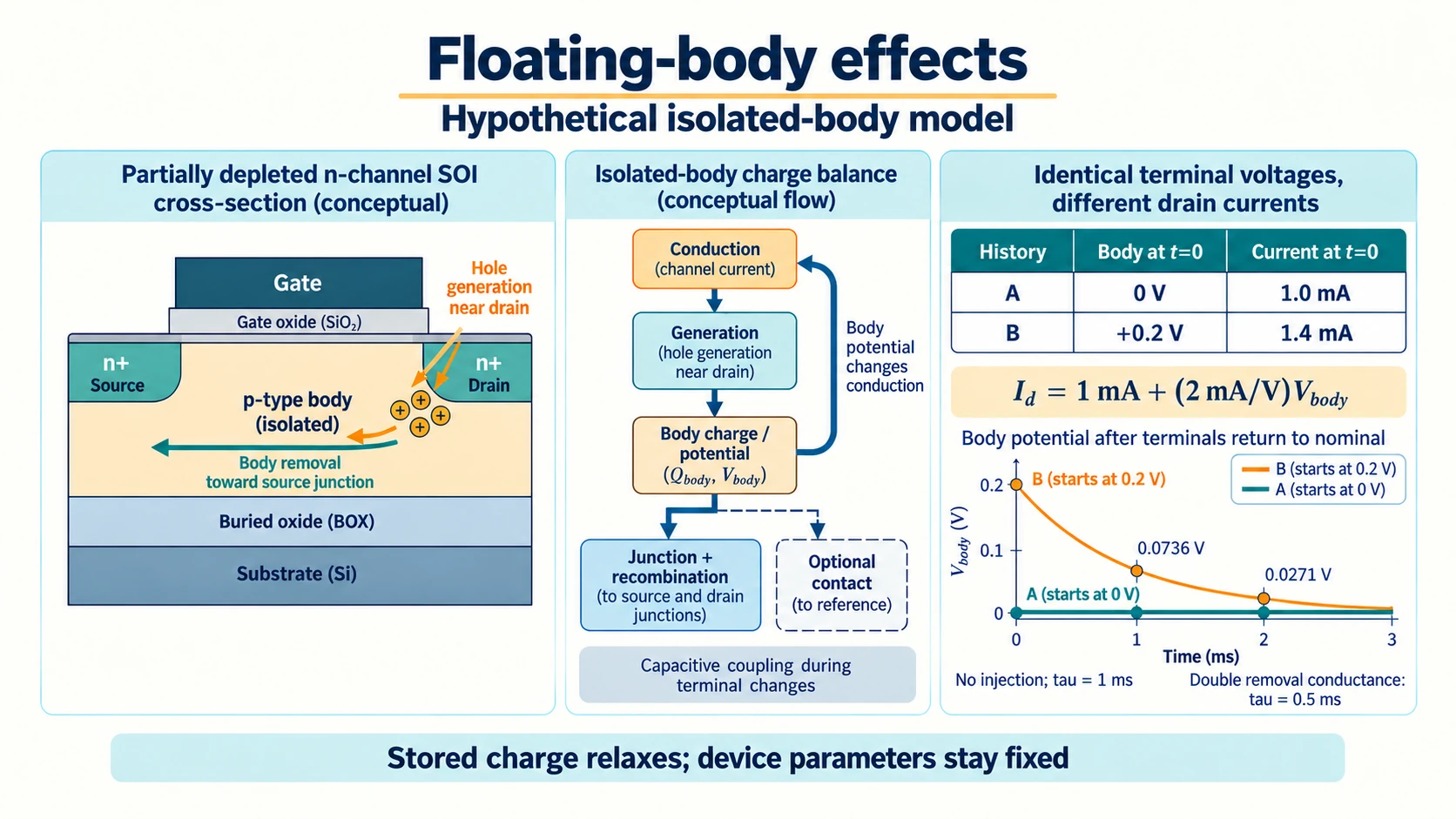
Repeating gate, source, and drain voltages does not necessarily repeat every internal electrical state. floating-body effects arise when an isolated body can retain charge and develop its own potential. That potential can alter subsequent conduction, so a terminal-voltage snapshot alone may omit information needed to explain drain current.
Use a stipulated n-channel, partially depleted silicon-on-insulator structure with a p-type body region. The examples are bounded electrical models, not measurements of a processor. Different SOI structures and body connections require their own analysis.
Compare connected and isolated silicon-on-insulator transistors
In the model, the buried insulating layer separates the active silicon from a conductive path into the underlying substrate. Source and drain junctions bound the p-type body region laterally. If a body contact holds that region near a defined potential through a stated impedance, charge can leave through that connection.
Without the body tie, the body is not automatically fixed at the source potential. It still exchanges charge through junction and generation or recombination processes, and couples capacitively to terminals. Electrically isolated does not mean incapable of any charge flow.
silicon-on-insulator transistors therefore need an explicit body boundary in the model. A structure with a connected body and one with an isolated body do not differ only in a displayed threshold number. Their charge-removal paths and available dynamic state differ.
The existence and size of a partially depleted body region are also relevant to this stipulated example. It should not be generalized into an identical behavior claim for every fully depleted or differently connected device called SOI.
Write a time-dependent charge balance
Let Q_body represent the modeled body charge state. Its rate of change is charge entering minus charge leaving under the chosen sign convention. Generation, junction currents, recombination, and any body-contact current must contribute according to the device boundary.
At a suitable drain bias, impact ionization in the stipulated n-channel device can generate holes that enter the p-type body. Jungemann and colleagues' "Impact of the Floating Body Effect on Noise in SOI Devices Investigated by Hydrodynamic Simulation" describes accumulated holes increasing the forward bias of the source/body diode and producing feedback. Their paper supplies mechanism background; the relaxation values below come from a separate linear teaching model.
Removal mechanisms prevent charge from growing without qualification. Junction conduction and recombination can change with body potential, while a contact can provide another path. The balance can settle, evolve, or respond to a later voltage history depending on those terms.
A fixed-terminal small-signal approximation can use an effective capacitance to relate charge changes to body-potential changes. With varying terminal voltages, capacitive coupling also belongs in the account. A constant-capacitance toy equation cannot be treated as a full semiconductor transport simulation.
Trace body potential into channel and junction behavior
Body potential relative to source can change the channel-control relationship. In the stipulated n-channel regime, a positive body shift can increase channel conduction at the same gate and drain biases through the body-voltage dependence. That is a state-dependent effect, not a change in the externally repeated voltage list.
The source-body junction also responds to the shifted potential. Increasing forward bias can change its current and contribute to charge removal or other coupled conduction. The research model describes feedback involving that junction, so the body balance and drain current are not necessarily independent equations.
If the applicable structure supports a parasitic bipolar contribution, source, body, and drain participate in another carrier path. Its importance must follow from the device and operating conditions, not from the word floating alone. The bounded explanation retains that possibility without claiming every isolated body enters the same regime.
The feedback connection can enter the charge balance through the generation term itself. A body-potential increase changes conduction, and under an applicable drain regime the changed carrier flow can alter how much charge is generated for the body. The resulting equation contains a potential-dependent injection as well as potential-dependent removal. Its equilibrium and transient response must be solved with those relationships, rather than assuming an independently fixed injection current.
Removal and junction behavior can limit the feedback response, and another operating regime can have different generation. A claim of unbounded growth or bistability would require additional analysis of those relationships. For the exponential interval below, injection stops so that the calculation isolates stored-charge relaxation.
The amplifier-slew-rate guide offers a diagnostic comparison for silicon-on-insulator transistors: a small-signal frequency plot cannot by itself establish large-output behavior. Here, repeating terminal voltages cannot by itself establish the isolated body state. Both explanations require evidence about the omitted condition. The slew guide calculates a sine wave's slope demand; the present model follows body charge and its effect on drain current.
Compare history-dependent drain current at identical terminal voltages
History A leaves the body near the stipulated reference state before applying the test biases. History B first applies a condition that supplies body charge, then reaches the same test gate, source, and drain voltages. Define the post-transition body potentials as zero for A and +0.2 volts for B.
Those internal initial conditions are stipulated after any terminal-coupling transient. They are not a prediction that every high-drain pulse produces 0.2 volts. At the common test boundary, both cases share the external voltages but retain different body state.
Use an illustrative local current relation I_d=I_base+g_body*V_body, with I_base one milliampere and g_body two milliamperes per volt. A then has one milliampere, while B initially has 1.4 milliamperes under this model.
history-dependent drain current follows from evaluating that same relation at different internal states. Fitting one current solely to the gate and drain voltages and applying it to both histories would omit V_body rather than explain its effect.
The Lenovo IdeaPad FHD Touch laptop listing describes a laptop with a 15.6-inch FHD Touch display, Core i5-1334U, and 16GB DDR4 memory. Its display can show common terminal voltages beside body states zero and +0.2 volts, with corresponding currents one and 1.4 milliamperes. Keep these stipulated initial states visible when comparing the histories. The specifications establish no floating-body measurement or processor mechanism.
A relaxation model shows reversible stored-state memory
For the common test interval, stipulate no further injection and a linear removal relation V_body/R through an effective leakage path. With effective capacitance C, the equation is C*dV_body/dt=-V_body/R. Its solution is the initial body potential times exp(-t/(R*C)).
Set the teaching time constant R*C to one millisecond. History B's 0.2-volt body state becomes approximately 0.0736 volts after one time constant and 0.0271 after two. The model's extra current decreases from 0.4 milliamperes to approximately 0.147 and then 0.0541.
The parameters remain fixed while the stored charge relaxes. The falling current difference therefore demonstrates reversible state evolution under the declared charge-memory model. Establishing a permanent threshold change would require a different state equation and evidence.
The relaxation can be more complicated in an actual device because its removal currents, capacitances, and continued generation need not be linear or constant. The exponential does not supply a universal recovery time for SOI transistors.
Stored charge and defect evolution need different evidence
A reversible body-state model and a model with changing device parameters can both produce dependence on prior operation. Repeating terminal biases and observing different current alone does not identify which mechanism caused it.
To support the floating-body explanation, retain evidence about the electrical boundary, charge balance, and potential-dependent current under the relevant history. A parameter-drift claim needs its own evidence. Neither should be inferred solely from an output curve that changed.
The peak-hold-response guide supplies a stored-state comparison for history-dependent drain current. Its detector acquires a voltage during a pulse, then loses part of that state before a delayed read. The transistor example also requires an initial state and matched observation times, but follows isolated-body charge instead of a peak detector's held voltage. Neither example supports a universal decay constant for the other apparatus.
A model can also need both states if the evidence supports them. Treating every observed memory effect as floating-body charge would overextend the mechanism beyond its defined boundary. The diagnostic should identify the specific state terms that explain the observation.
A body contact changes the dynamic model
Add a body-contact path with finite conductance to the reference. The balance now has another removal term, which can alter the equilibrium body potential and its response to injection. In the linear toy account, an additional conductance reduces the effective resistance and changes the relaxation time.
An ideal fixed-body boundary is a limiting approximation, not a description of every practical contact. A finite impedance can allow body motion under sufficient current. Its value and geometry need evidence for an actual device.
Changing that path does more than replace an extracted threshold constant. It changes where charge can go and how quickly the internal state evolves. A model that retains only a new static threshold can miss the corresponding transient behavior.
A body-contact comparison can be displayed on the ASUS Vivobook 14 FHD laptop, whose listing includes a 14-inch FHD display. Put injection, junction-removal and added contact-removal terms beside the body-charge equation, then compare the total conductance used in each relaxation calculation. The catalogue describes a computer with 16GB DDR4 memory and a Core 5 120U processor; these are workspace features. They supply no evidence for a transistor's body geometry, contact impedance or charge-removal rate.
Retain the state and observation boundary in a current claim
Align the observation times when comparing the two histories. A current measured immediately after B's transition and another measured long after A's transition do not describe the same elapsed-time boundary. The toy comparison uses common test biases and records the body initial condition at time zero, then evaluates both at matched elapsed times. That record exposes the internal-state difference rather than hiding it inside an unspecified measurement delay.
Record whether the body is tied or isolated, the preceding terminal history, and the body state after the transition. Evaluate both histories at the same elapsed test time under the stated removal equation. Hold device parameters fixed for the relaxation example; a claim that parameters changed requires separate evidence about that evolution.
A finite body contact adds another conductance in this linear account. With original leakage conductance G and added contact conductance G_contact, the time constant becomes C/(G+G_contact). Doubling the total conductance halves the teaching time constant to 0.5 milliseconds. After one millisecond, history B then reaches approximately 0.0271 volts and contributes 0.0541 milliamperes above the baseline. The changed removal boundary explains the faster relaxation while the assumed channel-current parameters remain fixed.